For those familiar with designing RF frequency generation circuits spurs are an unwelcome fact of life. The designer wants to generate a nice clean low noise signal but because of the way PLL’s work and other physical effects, the signal often also has other imperfections that ultimately degrade the radio performance. A key issue to be overcome are those of spurs, unwanted signals other than the desired frequency that mix with received or transmitted signals degrading performance parameters such as adjacent channel selectivity (ACS). Spurs are a particular concern in high performance radios where adjacent channel requirements are high, say 65 or 70dB as required to meet ETSI standards for PMR/LMR, or base station applications that often have higher performance requirements than the mobile terminals they serve. Even in systems with more relaxed specifications excellent ACR leads to the radio operating better in congested parts of the frequency spectrum.
Spurs, or spurious, are the result of numerous interactions in the phase lock loop and whilst the cause of some are obvious, others are more esoteric, harmonics and mixing products that find their way in to the output signal. When present they can render some channels unusable, an issue in systems that with many channels and where a user has paid for license fee for a block of frequencies, some of which are now unusable.
In Fractional N designs Reference and Integer Boundary Spurs (IBS) fall at known frequencies and so can be mitigated to an extent if these are calculated and compensated for. This can be an onerous task with many calculations required, especially when harmonics and mixing products are considered.
Much has been written about IBS, a quick Google on ‘Fractional PLL spurious’ reveals much comment and analysis. To minimize their effect or overcome them the designer usually reprograms the device to move the spur to a frequency that is either removed by the operation of the phase locked loop or away from the channels of interest. This requires changing the reference and signal division ratios, but these often have a limited range of values. Some vendors include a multiply/divide technique on the reference frequency path to enable more combinations to be used than just division alone but this still can have limitations. To overcome this the CMX940 High performance synthesiser with integrated VCO from CML is unique in that it implements a reference frequency synthesiser that is capable of generating far more options. In generating more options it also makes the number of possible calculations to avoid spurs increase as well which could mean a headache for the designer.
In order to avoid these issues CML provides a useful tool, the CMX940 PLL Simulation Tool for calculating phase noise and PLL settings in Octave. The PC GUI part of the tool provides an interactive environment for deriving PLL settings with spur avoidance.
Furthermore the tool is also integrated into the EV9400 evaluation kit, with a tab in the GUI that offers the user the ability to have a configuration generated that will avoid spurs without the need to run the calculator separately and write these setting directly to the device, allowing immediate evaluation of the solution, accelerating the product development task.
How the tool helps with mitigating spurs
The CMX940 Simulator Tool has a Spur Avoidance tab which will help any user to identify the output and VCO frequencies at which spurs occur and hence aid the user in getting spur-free performance.
The simulator will find all fractional spurs, up to and including those of the fifth order, and display them in a table on screen, as well as allowing the user to plot graphical results of the VCO and output spurs. For a more in depth look at the mathematics of the tool users can download the tool and documentation from the CML website https://www.cmlmicro.com/wp-content/uploads/2020/11/CMX940_Loop_Noise_Calculator.zip and view CML940 PLL sim tool.pdf “CMX940 PLL Simulation Tool”. Let’s now look at why this is such a useful tool to have:
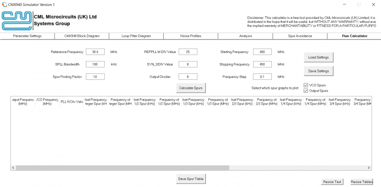
Our users, Alice and Bob, want an output frequency of 405 MHz from the CMX940 but are worried that there may be a spur that spoils the performance. They therefore decide to use the CMX940 Simulator. At first they use the settings pictured below and press the “Calculate Spurs” button.
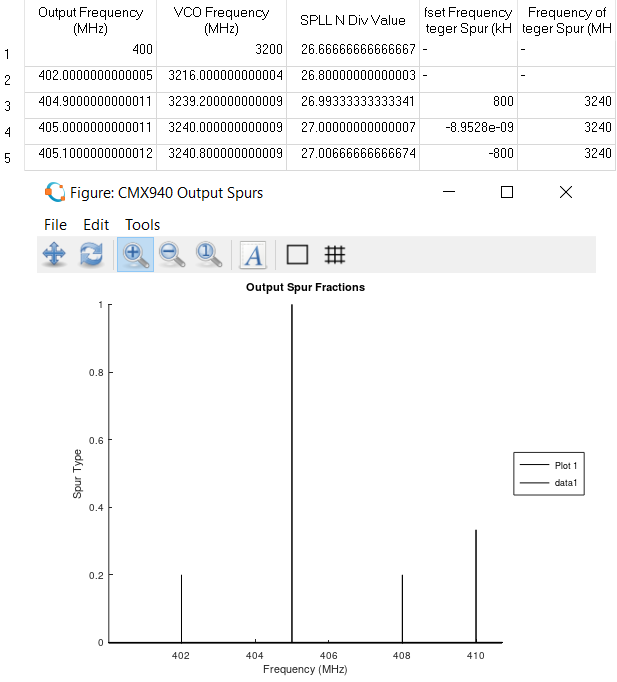
This generated a table which showed them that at the output frequency of 405 MHz an integer spur would be generated and the output spurs graph confirmed this!
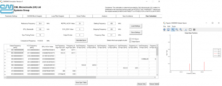
Therefore, Alice and Bob used a different set of values in order to try to find spur free performance. They chose to increase the REFPLL_MDIV value to 26 and SYN_SDIV value to 9. This gave the following results:
As you can see, the new spurs (in red on the output spurs graph) are not at 405 MHz and as the table of results does not list a value of 405 MHz, Alice and Bob have found a setting that is free of fractional spurs! This is a very quick process which means when they go to use the CMX940 there is no need to manually adjust settings to provide the spur-free performance required – all that is needed is a couple of minutes testing different options in the CMX940 Simulator.
For more information on the CMX940, visit the product page here.


