Wireline Telecom
CMX869B – Low Power V.32 bis Modem
The CMX869B is a multi-standard low power modem for use in EPOS terminals and telephone based information and telemetry systems. This highly integrated single-chip modem IC provides the functions needed to implement a ITU V.32 bis automode modem or a V.22 bis, V.22, V.21 and Bell 202, Bell 103 compatible modem operating under the control of external host timing for EPOS and other proprietary protocols.
The device integrates a V.32 bis automode modem, DTMF decoder, software-controlled output, ring detector, and line inputs and outputs that can be single ended or differential. Host control and data transfer is via CML’s C-BUS high-speed serial bus.
Devices are available through our Distributor Network.

Features
- V.32 bis/ V.32/ V.22 bis/ V.22 Automodem
– (14400, 12000, 9600, 7200, 4800, 2400, 1200 bps Duplex) - V.22 bis/V.22 Manual Modem
– (2400, 1200 bps) - V.23 (1200/75, 1200/1200, 75, 1200 bps FSK)
- Bell 202 (1200/150, 1200/1200, 150, 1200 bps FSK)
- V.21 or Bell 103 (300/300 bps FSK)
- High Performance DTMF Modem
- Single/Dual Tones Transmit and Receive
- ‘Powersave’ Standby Mode
- Asynchronous, Synchronous and HDLC Modes
Applications
- EPOS Terminals
- Telephone Telemetry Systems
- Remote Utility Meter Reading
- Security Systems
- Industrial Control Systems
- Electronic Cash Terminals
- Pay-Phones
- Cable TV Set-Top Boxes
Power Supply Requirement
- 3.0 to 3.6 V
Design Resources
CMX869B FAQ
Q. Can you help me understand the differences and migrate between the CMX869x families of devices?.
A. There are a number of minor differences between devices, to help explain these differences and make the most of the CMX869x please refer to the following application note: AN_Telecom_869B_Upgrade_1_August_06.pdf.
Q. How do I perform a V.32bit handshake with the CMX869B?
A. To originate a V32bis connection with CMX869A please follow the sequence illustrated below:
Reset and Power-up Sequence
Write GeneralReset
$01, no data
Write GeneralControlRegister(Reset=1,PwrUp=1)
$E0=0x0180
Wait 20ms
Write GeneralControlRegister(Reset=0,PwrUp=1)
$E0=0x0100
Set transmit and receive levels, b11:9 of $E1 and $E2 respectively.
The setting of these will depend on the line interface. For transmit, set such that signal level on line is –10dBm, the rest of this document will assume –4.5dB for Tx output (0b100).
For receive, a good starting recommendation is the maximum value, i.e. 0b111.
Go off hook
If using CMX869B relay drive.
$E0=0x0300
Wait 3 seconds
Dial number
Start handshake process
Set time limit for completion of connect sequence to 30 seconds
Select transmit QAM automodem mode, asynchronous 8 bit data no parity 1 stop bit
$E1=0xF816
Select receive QAM automodem mode, asynchronous 8 bit data no parity no overspeed.
$E2=0xFE36
Start QAM modem, originate at 14k4 b/s
$EA=0x0017
Monitor connect progress.
Check status register ($E6) bit 9 for QAM mode status change.
Check QAM status register for new status.
Leave when QAM status $EB= 0xXXX8 to 0xXXXF (value of bits 2:0 indicate connect bit rate), OR leave when 30 second timer expires.
Q. Why does the “carrier lost” status not appear when I remove the cable from the modem?
A. The Algorithm used within the CMX869B requires a minimum amount of received energy to be present with a long enough period of decodable data.
If the far end modem stops transmitting data (and therefore there is no carrier), the CMX869B can detect the lack of signal compared to the ambient noise level and so very quickly detect the loss of carrier and so issue the “carrier lost” status. This will also occur if the far end modem hangs up (as long as the two modems are connected through a switch / exchange).
However, if the local line to the CMX869B is physically broken, it will attempt to decode data from the noise energy at the input and indicate a “bad” or “very bad” SNR. At this stage the CMX869B cannot determine if the line has actually been broken, or is simply too noisy to support the current baud rate, and so will try to re-train to re-establish the connection.
The host should monitor the SNR readings from the CMX869B to determine if a baud rate increase or decrease is feasible, and implement a timeout for the condition where the SNR remains bad even after a re-train has been executed at the lowest baud rate selected. If the time-out expires, then the host should terminate the connection.
Q. I notice that during retrain/renegotiation attempts, the QAM Modem Status Register always indicates “rate negotiation” first, followed by “retrain request detected”. Why do these readings always follow one another?
A. The preamble for the rate re-negotiation request is 64 symbol periods of a particular data stream, the contents of which depend on whether the calling or answering modem is initiating the request. The preamble for the retrain request is at least 128 symbol periods of the same data stream as is used for the rate re-negotiation request.
The CMX869B sees the 64 symbol periods for “rate negotiation” first, as 64 symbol times completes before 128 symbol times does, so the device indicates, “rate negotiation request detected”. If the request is actually a “retrain request”, the preamble won’t stop there and will continue for at least another 64 symbol times…at the end of that period, the CMX869B will recognize the “retrain” request and update the QAM Modem Status Register accordingly.
Q. The “QAM Modem Status Register” (Section 6.9 of the data sheet) refers to “R1” through “R5”, yet I find no mention of these parameters in the data sheet. What are R1 through R5?
A. R1 through R5 are rate sequence specifiers that are used in the call establishment, re-train, and rate re-negotiation phases of a V.32bis data transaction. R1 through R3 are used for initial call establishment and re-training, while R4 and R5 are used for rate re-negotiation. These specifiers are fully described in the V.32bis specification that can be obtained from the ITU website.
Q. Are the QAM Modem Status Register contents valid when the 869B is NOT in QAM modem mode?
A. The contents of the QAM Modem Status Register are only valid when in QAM modem mode.
Q. If I enable the 869B for ‘automodem’ mode, will the device automatically and autonomously negotiate a connection with a remote modem, including a reduction in connection speed if required?
Yes, the ‘869B will auto-negotiate with the other end to the fastest bit rate that both can handle. The caveat here is that there is a limit as to how far down it will try to connect; the minimum connection speed depends on the selected standard , ie: if you start it off at 14.4kbps, it will only auto-negotiate down to 4.8kbps (ie: V32).
If you want the ‘869B to attempt a slower connection, you will need to manually configure the ‘ 869B for this.
Rate negotiation requests will be reported during the initial handshake procedure, and also if the far end issues a re-train or re-negotiate at any time, in which case the handshake will be automatically re-started in an attempt to get the highest speed possible on a given link. There should be no need for the host to take any action when it receives these messages, unless it causes a break in the data transfer while its going on.
Q. Concerning the notion that the chip will throttle back its speed to a minimum level determined by the standard, how will the host know that the handshake has effectively failed and that the device needs to be “manually” configured for lower speed connections?
A. If the CMX869B is set to 14k4 as its max connect rate, and it backs off to 4k8 and still cannot get a good connection, it will report a no-connect.
If the host wishes to try at 2k4 and 1k2, then it will have to issue a connection request with 2k4 as the max connect rate.
Q. If the far-end modem issues a re-train or re-negotiate request during the data session, will the 869B automatically and autonomously start the required handshake?
A. This will automatically be detected by the 869 and the ‘automodem’ process will be started automatically.
The 869B’s host will then see a data famine as this process runs, which could (wrongly) be interpreted as a loss of connection by the host. The host does not need to do anything to respond to a re-train or re-negotiate request except wait for it to complete and data transfer resume. Hence reading the QAM status register should be done regularly and the re-train request will be seen.
Q. I notice that the 869B connects but has “garbage characters” immediately after the connection completes, and I never receive “good data. What could be the problem?
A. It is imperative that the crystal frequency deviates from the nominal 6.144MHz by no more than the 100ppm laid down in the data sheet.
It must be stressed that the QAM algorithms are very sensitive to clock inaccuracy. Furthermore, if the crystal tolerance is outside of the required specifications, 1.2kbaud will sometimes work where all higher speeds produce high errors.
Internal tests indicate that a device with an inaccurate clock would connect OK with a reasonable SNR result in the QAM Modem Status register, but the receive SNR would quickly start to drop until the received data had a high error rate.
In some cases the errors would start almost immediately after connection was established.
Measuring the crystal frequency directly is somewhat difficult in that any probe adds some capacitance to the pin and shifts the frequency of oscillation.
There is an indirect test that can confirm if crystal tolerance is a problem.
Once a connection has been established, periodically read the SNR result from the QAM Modem Status register; if the SNR degrades, the crystal tolerance is likely a problem.
CMX869B DAA Circuit with Line State Detection
The circuitry used to connect a modem to a telephone line, also referred to as a “direct access arrangement” or DAA, can represent a significant hurdle for some customers. To assist these customers, this application note describes one method of connecting the CMX869B to the telephone network using low-cost components. In addition to the basic DAA function, other circuitry is provided for the CID and 911 detection functions.
CMX868A, CMX869B Modems with CLARE Litelink DAA
This application note describes how the Clare CPC5621 optical DAA can be used to interface the CMX868A V.22bis and CMX869B V.32bis modem chips to the telephone line. The primary benefit of the Clare LightLink DAA is that it requires very little board area and has a very low profile. This can be important in applications where there are tight space constraints.
CMX86x and CMX850 Filter Coefficient Generator Program
This application note comprises the Filter Coefficient Generator program as an Excel spreadsheet as well as operational instructions.
CMX869x Modem Series Upgrade Path
The CMX869x modem series provides the functions necessary to implement a V.32 bis automode modem and includes all of the signaling likely to be required within the General Switched Telephone Network, GSTN or PSTN. Some applications normally use a low data rate for regular traffic but require a much higher data rate for occasional traffic. To support such applications the original CMX869 specification has been extended through the CMX869A and CMX869B. There are no pin-out or signal differences between the CMX869x devices so they may be used interchangeably in the same hardware. However, extending the function set required minor register bit re-assignments that affect firmware portability. The aim of this document is to illustrate these changes and to detail the migration of code between devices in the series.
CMX869B - Bell 212A Implementation
The CMX869B V.32bis modem IC from CML Microcircuits offers multiple modem protocol support in both automodem and manual modes, a rich telephony feature set, and low power consumption. The purpose of this document is to describe how Bell 212A can be supported using the V.22 mode of the CMX869B modem IC.
CMX869x Caller Line ID
CLI operates in two distinctly different modes, on-hook and off-hook, which are often referred to as type 1 and type 2 respectively. The on-hook mode is the most widely used because the CLI is delivered before the call is accepted. Here the calling parties identity may be used within the system in a decision making process. For example, a simple call filter that rejects calls from callers who withhold their own number. Off-hook systems find more limited use because the target function is to let the called party know the identity of a missed caller. This document covers only on-Hook or type 1 CLI although the principles may be extended for some type 2 services.
CMX8xx: Short Message Service (SMS) Implementation using CML Products
This document aims to assist modem product designers using and understanding Short Message Service (SMS) applications. CML Microcircuits' (CML) integrated circuit devices (CMX85x and CMX86x) could be used to realize and achieve a Caller Line Identification (CLI), SMS or Low Rate Messaging Service (LRMS) data transfer within a wireline system.
Recommendations for V.23 1200/75 b/s duplex call set-up
V.23 recommendations do not describe how a connection is established; a procedure is described below and illustrated in Figure 1; however you should not rely on other modems following this particular flow. Note also that 1200/1200 bps half-duplex connections are not covered by this application note.
CMX867 - V.22 Full Duplex Call Set Up
This document provides details on the V.22 wire-line communications
View
V.22bis Full Duplex Call
This document provides details on the V.22bis wire-line communications protocol
View
| DE8691 | 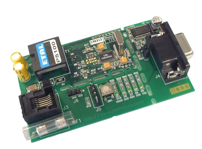 |
The DE8691 Demonstration Board features the CMX869B V.32 bis modem IC in a “socket modem format” implementation. The “socket modem” section also contains the line interface components and a Flash PIC µC.
|
DE8691_Product_Preview
|
CMX86x: Tone Generator Calculator spreadsheet.
An Excel spreadsheet that calculates the values required for the Programmable Tone Generators. Single tones and dual-tones are allowed. The spreadsheet predicts the actual frequency and amplitude of each tone.
C-BUS Guides
Guides to operation and interfacing
DE8691 Board Schematics
DE8691 Support Files
Support Files for the DE8691 Demonstration Kit