Wireline Telecom
CMX867A – Low Power V.22 Modem
The CMX867A is a multi-standard V.22 modem for use in telephone based information and telemetry systems.
Control of the device is via a simple high speed serial bus, compatible with most types of µC serial interface.
The data transmitted and received by the modem is also transferred over the same serial bus.
On-chip programmable Tx and Rx USARTs meeting the requirements of V.14 are provided for use with asynchronous data and allow unformatted synchronous data to be received or transmitted as 8-bit words.
A high quality DTMF decoder with excellent immunity to falsing on voice, and a standard DTMF encoder are included. Alternatively, these blocks can be used to transmit and detect user-specific, programmed single and dual-tone signals, call-progress signals or modem calling and and answering tones.
Flexible line driver and receive hybrid circuits are integrated on chip, requiring only passive external components to build a 2 or 4-wire line interface.
The device also features a Hook Switch Relay Drive output and a Ring Detector circuit which continues to function when the device is in the Powersave mode, providing an interrupt which can be used to wake up the host µController when line voltage reversal or ringing is detected.
Devices are available through our Distributor Network.

Features
- V.22/Bell 212A 1200/1200 or 600/600 bps DPSK
- V.23 1200/75, 1200/1200, 75, 1200 bps FSK
- Bell 202 1200/150, 1200/1200, 150, 1200 bps FSK
- V.21 or Bell 103 300/300 bps FSK
- DTMF/Tones – Tx and Rx
- Low-Power Operation with Standby Mode
- Software and Hardware compatible with CML’s CMX868/868A
Applications
- Telephone Telemetry Systems
- Remote Utility Meter Reading
- Security Systems
- Industrial Control Systems
- Electronic Cash Terminals
- Pay-Phones
- Cable System TV Set-Top Boxes
Power Supply Requirement
- 2.7 to 5.5 V power supply
Downloads
Design Resources
CMX867 and CMX867A FAQ
Q. I see that both the CMX867 and CMX867A are now CML products. Can you tell me what the difference is and whether I would have problems migrating from my existing CMX867 design to an CMX867A based unit.
A. There are three major changes:
a The DTMF decoder performance has been improved to give greater compatibility with worldwide exchanges and with the DTMF encoders supplied by other manufacturers. The dynamic range has been increased to improve the compatibility with normal transmission conditions, particularly where lines are encountered. The acceptable twist has been increased to cope with low-cost DAAs and lines. Additionally the algorithm has been extensively modified to provide a high immunity to voice signals.
b The hybrid function has been improved to increase rejection of transmitted signals and harmonics and to reduce the number of components in the DAA, and to simplify the design of DC-coupled DAAs.
c A transmit output tri-state capability has been added where the outputs of the CMX867A are independently tri-stateable allowing the line and, hence, the receiver to be biased, without terminating the line.
Caller-ID signals flowing through a hook-switch bypass capacitor will see a high impedance termination, which gives a better match to the receiver input. This method offers the possibility of improved S/N performance over other low-cost approaches available.
A current design that uses the CMX867 can use the CMX867A, as the IC should be considered a drop-in replacement. The additional features should appear invisible to existing software and hardware designs.
Q. I see that the CMX867A datasheet / data bulletin has a paragraph that discusses the need for an additional 7dB of “trans-hybrid” loss. What is this talking about, and why do I need it?
A. The trans-hybrid loss refers to attenuation of the Tx output signal that gets fed back into the Rx input path of the same device. If the 7dB trans-hybrid loss is not provided then the sensitivity in originate mode will be reduced from the minimum “must detect” value of -43dB. This reduction in sensitivity is due to 2400Hz carrier rejection in the receiver path being around 36dB. While the addition of 7dB of trans-hybrid loss will result in optimum performance, neglecting the additional 7dB of trans-hybrid loss will not prevent operation and may be acceptable in some applications.
Q. I have been trying to program the CMX867A Programming register, but it does not seem to work. What is the suggested method of writing to this register?
A. Writing to the Programming register is performed via the CML C-BUS.One register address is required for each data word:
You must also ensure that the programming flag bit in the Status register is set before writing to the Programming Register.
The process is as follows:
- Address for programming register ($E8) sent on Command Data line
- First word for the programming register is loaded onto Command Data line
- Check the Programming Bit Flag in the Status Register – b13 = 1; if true then continue
- Address for programming register ($E8) sent on Command Data line
- Second Word for the programming register is loaded onto Command Data line
- Check the Programming Bit Flag in the Status Register – b13 = 1; if true then continue
- Address for programming register ($E8) sent on Command Data line
- Third Word for the programming register is loaded onto Command Data line
Continue:
Note:
If the latency between writes is long, typically greater than 150us it is not required to check the Status Register bit flag (please refer to the data sheet).
Q. How do I detect CAS on the CMX868A, CMX867A or CMX860?
Q. Can I do Type 2 CID (Caller Identity) on the CMX868A, CMX867A or CMX860?
A. The Programmable Tone Pair can detect the CAS tone required for type 2 CID but an unacceptable tendency to false is likely. This is because both filters are likely to ring due to the narrow bandwidth required. The CMX602B provides a very efficient CAS detector that can be interfaced through the CMX868, CMX867 and CMX860. The method described does not require any additional connections to the host microprocessor and very few additional components.
The CMX602B input signal is derived from the same signal input as the CMX86x. The gain components around the CMX602B may need to be adjusted. See the CMX602B Data Sheet for more information.
The CMX602B Mode input is clamped to Vss so that its mode is selected by the state of the ZP input. When the CMX86x is powersaved or on-hook, the CMX602B will be powersaved. When the CMX86x goes off-hook the CMX602B will come out of powersave and go into CAS detect mode.
The CAS should be detected around 55ms after it starts and DET will go low. This will cause the CMX86x to detect a ring signal. The Ring Detect flag will go low and the CMX86x will generate an interrupt (provided this interrupt is un-masked). This method allows the CAS detector to be polled and the interrupt to be masked. Polling is necessary to measure the length of the CAS to qualify it.
The software must remember to differentiate between a genuine ring detect and a CAS detect.
CAS Detection Method
The CMX86x will be off-hook.
Approximately 55ms after the start of the CAS the CMX86x will signal a ring detect. Ring Detect will go high (Status Register ($E6) b14 = 1) and, if unmasked ((General Control Register ($E0) b5 = 1), an interrupt will be signalled.
The Interrupt should be masked and Ring Detect polled to confirm that the CAS is present for the expected period.
Following the CAS detect a short period of silence occurs during which the near end handset is muted. Any line activity can be confirmed by polling the Energy Detect flag (Status Register ($E6) b10). This is important to help reduce the incidence of false CAS detection.
The Ring Detect interrupt should be masked for the remainder of the CID transaction.
Please note the CML disclaimer notice for applications and FAQ information.
Copyright © 2013 CML Microsystems Plc – All Rights Reserved
CMX86x and CMX850 Filter Coefficient Generator Program
This application note comprises the Filter Coefficient Generator program as an Excel spreadsheet as well as operational instructions.
CMX8xx: Short Message Service (SMS) Implementation using CML Products
This document aims to assist modem product designers using and understanding Short Message Service (SMS) applications. CML Microcircuits' (CML) integrated circuit devices (CMX85x and CMX86x) could be used to realize and achieve a Caller Line Identification (CLI), SMS or Low Rate Messaging Service (LRMS) data transfer within a wireline system.
CLI with the CMX860, CMX865/A, CMX867/A and CMX868/A
Caller Line ID (CLI) was originally developed for the US market but has become commonplace throughout the World because of its multitudinous applications. There are a number of CLI protocols to which telephone equipment manufacturers must comply. This document gives an overview of two types; BELL GR-30-CORE/SR-TSV-002476 (or ETSI 300 659-1 section 6.1.1) used in the USA and most of the world and Caller Line Identification Presentation (CLIP) BT SIN 227 (or ETSI ETS 300 659-1 section 6.1.2c) used in the UK.
Recommendations for V.23 1200/75 b/s duplex call set-up
V.23 recommendations do not describe how a connection is established; a procedure is described below and illustrated in Figure 1; however you should not rely on other modems following this particular flow. Note also that 1200/1200 bps half-duplex connections are not covered by this application note.
CMX867/A and CMX868/A V.22bis and V.22 modem design guide
The CMX868 & CMX867 V.22bis/V.22 Modem design supports rapid development and manufacture of ultralow power CMX868-based V.22bis and CMX867-based V.22 modems. This design has been optimized for a variety of applications including set top boxes, point-of-sale (POS) terminals and security systems. These documents are provided to assist users who are creating their own circuit designs.
View
CMX867 - V.22 Full Duplex Call Set Up
This document provides details on the V.22 wire-line communications
View
| PE0003 | 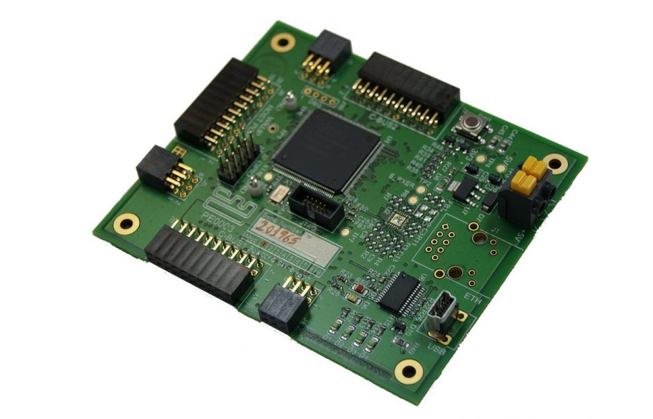 |
The PE0003 Evaluation Kit Interface Card is a global interface system for use with evaluation kits for CML’s new generation ICs, including FirmASIC™ based products. | PE0003_User Manual
|
| DE8681 | 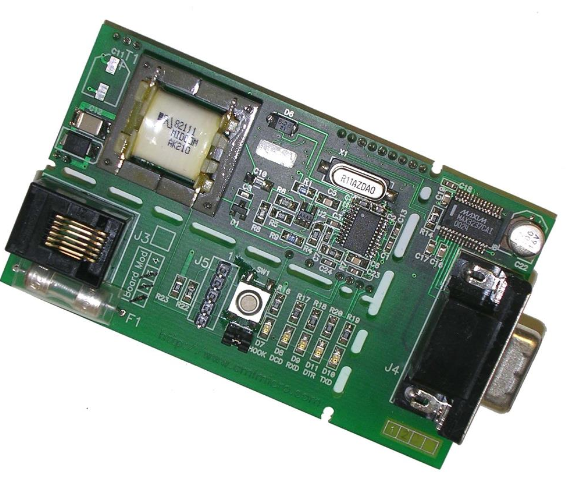 |
The DE8681 Demonstration kit is a reference design for the CMX865A DTMF Codec/FSK combo, CMX867A Low Power V.22 modem and CMX868A V.22bis modem IC. | DE8681_Product_Preview
|
CMX86x: Tone Generator Calculator spreadsheet.
An Excel spreadsheet that calculates the values required for the Programmable Tone Generators. Single tones and dual-tones are allowed. The spreadsheet predicts the actual frequency and amplitude of each tone.
C-BUS Guides
Guides to operation and interfacing